Table of Contents
Inductance
| Stan Zurek, Inductance, Encyclopedia Magnetica, https://e-magnetica.pl/doku.php/inductance, {updated: 2025/09/07 00:15} |
* This page is being edited and may be incomplete or incorrect.
Inductance, L - a physical parameter of an electric circuit or a component which quantifies its ability to store energy in the magnetic field, due to electric current causing the field.1)2) Inductance is the electrical dual of capacitance.3)
Inductance represents inertia in an electric circuit4)5)6)7)8)9) because it opposes change of electric current $I$ in time $t$, so that electromotive force $\mathcal{E}$ (a type of voltage) is required for such change to occur.10) The proportionality coefficient between these values is the inductance $L$, which it is measured in the units of H (henry) in the SI system, such that H ≡ V·s/A. The unit is named after Joseph Henry, an American scientist who studied inductive effects.11)
| Relationship between inductance L and other physical parameters (in a linear circuit) | |
|---|---|
| $$L = - \mathcal{E} · \frac{ΔI}{Δt} $$ | (H) |
| where: $\mathcal{E}$ - electromotive force across the inductance (V), $ΔI$ - change of current (A), $Δt$ - change of time (s) | |
Ideal inductance has zero electrical resistance, but in real inductors there are parasitic properties such as resistance and capacitance.
Various types of inductance can be defined for various aspects of electric circuits and electromagnetic devices, and they have very specific physical meanings, as detailed below: self-inductance, mutual inductance, leakage inductance, internal inductance, external inductance, total inductance, etc.12)13)14)
An electric circuit containing inductance and capacitance can exhibit resonance, and this property is exploited for example in signal filtering, conversion of energy, transmission and reception of electromagnetic waves15), and in plethora of other technical applications.

S. Zurek, E-Magnetica.pl, CC-BY-4.0
S. Zurek, E-Magnetica.pl, CC-BY-4.0

| → → → | Useful article? Please link to this page to help us grow.  | ← ← ← |
|---|
Inductance in electric and electronic circuits
Inductance symbols

1) as per IEC 6061716),
2) coupled inductance or transformer with the additional line denoting magnetic core and dots representing polarity of windings17),
3) variable inductance 18),
4) alternative symbol19),
5) simplified rectangular symbol20),
6) simplified shaded rectangular symbol21)
Electric and electronic diagrams use multiple symbols which represent various inductive component. The most frequently used symbol is made from 3 or 4 semi-circles (more popular in IEC standards)22)23), or overlapping partial circles (more popular in ANSI standards).24)25)
In theory, standards such as IEC 60617 define the symbol for inductance (or inductor) as having 4 semi-circles26), but in practice there is such a variety of inductive components that there are many symbols, with additional sub-symbols and their combination, for example:
- dot - denotes magnetic polarity of the given coil or winding
- angled arrow - denotes variable inductance
- parallel straight line (dashed, solid, or double) - denotes magnetic core
- empty or solid rectangle - in IEC countries it can be used as a generic representation of impedance (and hence also of inductance) or magnetically coupled windings
Many other symbols are in used, especially when multiple areas of engineering are compared (electronics, energy transmission, fault protection, high-frequency and RF circuits, etc.) Unless the rectangular symbol is used, most of other symbols include at least one semi-circle or 3/4 circle for representing inductive conductor, coil or winding.
Dot notation

S. Zurek, E-Magnetica.pl, CC-BY-4.0
The dot notation is directly important for magnetically coupled inductances, so that the circuit designers, and component or device manufacturers can have shared understanding of the polarity of connections. In the generic sense the dot polarity designates just the relative direction of voltage drop between the coupled windings. This is important for example in polarity-sensitive connections such as in transformers or flyback converters.27)

S. Zurek, E-Magnetica.pl, CC-BY-4.0
In a manufacturing sense the dot notation can be used on a technical drawing to denote the start of the winding (e.g. as manufactured on a winding machine). However, this can be only utilised if all the coupled windings are physically wound in the same direction. If the direction of winding is reversed then such winding will also have reversed polarity. Therefore in manufacturing regime both the starting point and the direction of rotation are important.
A dot or other marker (cross, square, semi-circle, etc.) is also used on magnetically non-coupled inductor (with a single winding). This notation is helpful especially for inductors multi-layer coils, because in switch-mode converters the switched node of the inductor can radiate electromagnetic fields and can lead to electromagnetic-compatibility issues (EMC, EMI). Therefore, inductor polarity is important in such cases for the designers of such circuits.

S. Zurek, E-Magnetica.pl, CC-BY-4.0

S. Zurek, E-Magnetica.pl, CC-BY-4.0
Role of inductance in circuits
Inductive components perform a multitude of roles in electric and electronic circuits, including unwanted effects. They all stem from the energy storing capability as such, but resulting in specific signal and power effects required by the designer of the circuit. It is not possible to list all the uses, so just a few examples will be given.
Filtering

S. Zurek, E-Magnetica.pl, CC-BY-4.0
Inductances stores energy in its magnetic field and opposes changes of electric current. Therefore, if an inductance is added to a circuit in which a current pulsation occurs, then it will slow down increase of current, and it will also slow down reduction of current, thus providing filtering capability.
In a series-connected RL circuit the higher frequency variations will be smoothed out by the presence of inductance, thus resulting in a behaviour of a low-pass filter.29)
Inductance-based filtering is widely used with simpler components (inductor, choke) as well as with more complex ones (common-mode choke, LC filter).30)
Transformation and power conversion
Pulsating or alternating currents can be converted through self or mutual inductance to a different level of voltage/current with very high efficiency of transformation. This is widely used for distribution of electric energy, in high-voltage grids (power transformer), as well as DC circuits in which inductors are ubiquitous (SMPS).
Galvanic isolation
Magnetic coupling through mutual inductance is equivalent to passing electric energy between two circuits, which do not have to be galvanically connected to each other. Therefore, full galvanic isolation is possible, and it is widely utilised for safety transformers (e.g. in SELV systems). This is a benefit separate from transformation to a different level, because 1:1 transformers are also used for the sole purpose of galvanic isolation for safety (or elimination of circulating DC currents).31)
Tuned LC circuits

S. Zurek, E-Magnetica.pl, CC-BY-4.0
Tuned RLC circuits rely on the effect of resonance, in which the energy oscillates between the two components: inductance L and capacitance C.33) With high-quality resonance the amplitude of oscillations can be much higher than the signal penetrating the LC circuit (either electrically or electromagnetically).

This property is used for transmission of electromagnetic waves (radio waves), which can propagate over extremely large distances, and thus are used for telecommunication (e.g. through satellites orbiting around the Earth).
Wireless digital communication is based on the same principle of resonating LC circuits, because even though the signal processing is digital, the actual physical signals in space must be sent through the sending and receiving antennas which operate in a fully analogue way.36) 37)
For example, a transmission line exhibits distributed parasitic inductance and capacitance between its conductors. If these conductors are separated then similarly the parasitic inductance and capacitance can be used as stretched-out and distributed LC tank, which can resonate at a specific frequency and efficiently couple to a specific sub-multiples (λ/2 or λ/4, etc.) of a given wavelength (dictated by the oscillating frequency).
Inductance and resonance
Resonance can occur only if the given circuit has at least one element which stores the equivalent of kinetic energy and another one which represents the potential energy, and in an electric circuit these are L and C, respectively.

A simplest circuit capable of resonating is a series connection of three components: R, L, C, as illustrated. When a DC voltage source is provided, once the switch is closed the circuit can respond in several ways, as dictated by the ratio of the four parameters (voltage, resistance, inductance, capacitance).
Examples of possible types of responses (i.e. the current flowing in the circuit after the switch is closed) are illustrated by the waveforms shown below. For the applied DC step voltage the notable cases are:38)
- For just pure L in the circuit (R = 0, C = shorted out) the current increases linearly to infinity.
- For R + L (C = shorted out) the current increases exponentially as $I(t) = \frac{V}{R}·(1-e^{-t/τ})$ where $τ = L/R$ is the characteristic time constant.
- For pure L + C (R = 0, and without radiation) the oscillations at frequency $f = \frac{1}{2·π·\sqrt{L·C}}$ have the same peak as the applied voltage and continue indefinitely (undamped case).
- For R + L + C combination three cases are possible, depending on the relative value of R:
- for low R such that $R < 2·\sqrt{L·C}$ multiple oscillations (or at least one undershoot) with their amplitude decaying to zero (underdamped),
- for medium R such that $R = 2·\sqrt{L·C}$ no oscillations (not a single undershoot), with the amplitude decaying to zero with the fastest rate (critically damped),
- for high R such that $R > 2·\sqrt{L·C}$ no oscillations (not a single undershoot), with the amplitude decaying more slowly that for any of the previous cases (overdamped).
For the damped cases the frequency of oscillations is slightly lower than for the undamped case.39)
1) pure inductance, current increasing linearly (L = 1 H, R = 0 Ω, C = shorted out)
2) RL circuit, exponential charging with time constant $τ = L/R$ (L = 1 H, R = 1 Ω, C = shorted out)
3) pure LC resonance, undamped, infinite oscillations (L = 1 H, R = 0 Ω, C = 1 F)
4) real RLC resonance, underdamped, decaying oscillations (L = 1 H, R = 0.5 Ω, C = 1 F)
5) real RLC resonance, critically damped, no negative undershoot (L = 1 H, R = 2 Ω, C = 1 F)
6) real RLC resonance, overdamped, slower decay than critically damped (L = 1 H, R = 4 Ω, C = 1 F)

S. Zurek, E-Magnetica.pl, CC-BY-4.0
Physical definition of inductance

S. Zurek, E-Magnetica.pl, CC-BY-4.0
Inductance is said to be a “geometrical factor”,40)41) because for linear systems (e.g. such that do not exhibit magnetic saturation) the value of inductance does not depend on the amount of current flowing through the circuit. However, for non-linear systems the inductance can vary over a very wide range, for example as dictated directly by the variability of the magnetic permeability of magnetic circuit associated with the given inductance.
According to the Ampere's law, moving electric charges or electric current generate magnetic field which circulates around this current.42)
However, the presence of magnetic field in a given volume of space or material is synonymous with some energy being stored in that volume.43) Therefore, the inductance quantifies the correlation factor between the energy stored in the magnetic field, and the current that produces it. Field generated externally (by other circuits) does not contribute to inductance.
| Inductance as a geometric factor 44) | |
|---|---|
| $$ L = \frac{2·E_H}{I^2} $$ | (H) |
| where: $E_H$ - energy (J) stored in magnetic field produced by the electric current $I$ (A) | |
In an electric circuit that possesses some inductance a constant value of current (DC) produces a constant magnitude of magnetic field, and therefore constant amount of energy. The energy is stored in the magnetic field and therefore for a lossless system (e.g. a superconducting wire) there is no voltage needed to sustain the current.
But any change of the amount of energy stored in the magnetic field due to the current requires delivering or extracting the energy from such circuit, which will require change of current and the voltage proportional to it, because electrical energy is proportional to current and voltage so both quantities must be non-zero for the energy to be exchanged.
Magnetic permeability
Magnetic field contains energy whose density per volume can be calculated with the following equation (for a medium with a constant permeability).45)
| (14a) | $$E_{vol} = \frac{μ_r · μ_0 · H^2}{2}$$ | (J/m3) |
| (14b) | $$E_{vol} = \frac{B · H}{2}$$ | |
| (14c) | $$E_{vol} = \frac{B^2}{2· μ_r · μ_0}$$ | |
| units: H (A/m), B (T) | ||
Calculation of inductance
Derivation of an equation for inductance is therefore based on the information about the distribution of electric current for a given geometric configuration. The simplest configuration is a straight piece of conductor with some wire flowing through it. However, theoretical considerations show that the value of magnetic field decays proportionally to reciprocal of distance from such wire, which leads to an expression with infinite energy, and thus infinite inductance.46) This is because in a real circuit the current must flow in a closed circuit (which is also required from the viewpoint of charge conservation), thus forming at least a magnetic dipole, for which the magnetic field decays with the square of distance from it (at large distance), and makes the expression finite for energy, and for inductance.47)
Therefore, in textbooks the derivation is usually carried out for a current loop48)49) or magnetically coupled two loops, because explanation of inductance is in some sense easier if carried out first for the mutual inductance.50)51)
This leads to deriving a formula based on magnetic vector potential as below, which involves volume integration, and thus can be evaluated analytically only for simple geometries.
| Inductance as a geometric factor 52) | |
|---|---|
| $$ L = \frac{1}{I^2} \int_V{\vec{j}·\vec{A}} ~ dV $$ | (H) |
| where: $I$ - electric current (A), $\vec{j}$ - vector of current density (A/m2), $\vec{A}$ - magnetic vector potential53) (V·s/m), $V$ - volume (m3). | |
Flux linkage

S. Zurek, E-Magnetica.pl, CC-BY-4.0
The concepts of magnetic flux $Φ$ and magnetic flux linkage $λ$ is used as an alternative, and more direct method for calculation of inductance.55)56)57)58) Because magnetic field is produced around a conductive path with current, then by the reciprocal argument, also if magnetic field penetrates the same conductive path there would be a current induce in it. This expression is useful in practice, because flux and flux linkage can be measured for physical circuits, and therefore inductance can be measured directly.
| Inductance vs. flux and flux linkage59) | |
|---|---|
| $$ L = \frac{N·Φ}{I} = \frac{λ}{I} $$ | (H) |
| where: $N$ - number of turns of a coil (unitless), $Φ$ - magnetic flux (Wb), $I$ - electric current (A), $λ$ - magnetic flux linkage (Wb-turns) | |
However, the concept of flux linkage can be extended also to a straight piece of conductor, because if the current produces magnetic field and magnetic flux around itself, then this flux is linked to the current that produces it. And because the field/flux from each infinitesimal fragment of conductor in general links to each other infinitesimal fragment, then this gives rise to a mutual inductance even at the fundamental level, thus giving rise to the self-inductance, as well as mutual inductance to other circuits.
Analytical

Geometric mean distance (GMD) is a useful concept for calculating mutual, and partial internal self-inductance. GMD is computed by multiplying all the considered pairs of distances over specific area(s) of interest, and taking the n-th root of the value. For simple configurations such as two rectangles, the value of GMD is smaller than AMD (arithmetic mean distance).
| GMD - Geometric Mean Distance 60) | |
|---|---|
| $$ GMD = \lim_{n→∞} ( d_1 × d_2 × ... × d_i × ... × d_n )^{1/n} = \lim_{n→∞} \left( \prod_{i=1}^{n} d_i \right)^{1/n} $$ | (m) |
| where: $d_i$ - i-th distance (m) between the two filaments, $n$ - number of filaments considered (unitless) | |
To calculate the combined mutual partial inductance $M_p$ this expression has to be evaluated (integrated) between the two areas A, A' of the two conductors. For very long filaments $l >> d$ the only parameter that varies is $d$.
$$ M_p ≈ \frac{μ_0}{2·π} · l · ( ln (2·l) - 1) - \frac{μ_0}{2·π}·l· \frac{1}{A·A'}· \int_A \int_{A'} ( \ln d) ~ dA' ~~ dA $$
which can be shown to be equivalent to:
$$ M_p ≈ \frac{μ_0}{2·π} · l · \left( \ln \frac{2·l}{GMD} - 1 \right) ~~, ~~~~ (for ~~ l >> GMD) $$
The same equation applies to calculating partial internal self-inductance, but the GMD is calculated for the given area of the conductor with respect to itself. This approach shows the utility of the geometric mean distance GMD parameter.61)
The actual formulas depend on the considered shape(s), and therefore can be analytically derived respectively for each shape. These equation are listed in the literature (for example in references: 62)63)64)), and some of the interactive calculators are provided in → Calculators of inductance.
| |
In a coiled conductor with turns connected in series (such as a solenoid), the magnetic flux from each has some flux linkage to each other turn, and the effect is such that the self-inductance becomes proportional to the square of the number of turns:65)
| Inductance of uniform closed magnetic circuit 66) | |
|---|---|
| $$ L = \frac{μ_0 · μ_r · A · N^2 }{l} $$ | (H) |
| where: $μ_0$ - permeability of free space (H/m), $μ_r$ - relative permeability of magnetic medium (unitless), $A$ - cross-sectional area (m2), $N$ - number of turns (unitless), $l$ - equivalent magnetic path length (m) | |
Numerical
Finite-element modelling (FEM) relies on subdividing the region of space into many small subregions, by using the mesh. The appropriate subregions of space can be the integrated numerically over the considered volume of conductor(s), so that the self of mutual inductance can be derived from these numerical integrals, which involve the magnetic vector potential $A$, current density $J$, volume $V$, and current $i$. Therefore, self-inductance can be numerically calculated as:67)
$$L_{self} = \int_{V} \frac{A · J · dV}{i^2} $$
The mutual inductance $M_{12}$ between the first and the second coil can be calculated by setting the current in the second coil to zero, and integrating the $A_1 ·dV_2$ component caused by coil 1 in the volume of coil 2:
$$ M_{12} = \frac{N_2}{I_1 · a_2} · \left( \int_{J_{2}} A_1 · dV_2 \right) $$
where: $N_2$ - number of turns of coil 2 (unitless), $i_1$ - current in coil 1 (A), $a_2$ - cross-section area of coil 1 (m2), $J_2$ - current density (A/m2) in coil 2, $A_1$ - the component of magnetic vector potential contributed by coil 1, $V_2$ - volume of coil 2 (m3).
Types of inductance
There are various types of inductance that can be identified as needed for the given type of analysis, and some of the most important types are described in the sections below. The are multiple more definitions, so this list is non-exhaustive, but rather illustrative.
Self-inductance

S. Zurek, E-Magnetica.pl, CC-BY-4.0
The name self-inductance is used specifically for the inductance of a given electric circuit without considering any magnetic coupling to other circuits. However, inductance is not concentrated at a specific point in space but it is contributed to by all the volume of space occupied by the magnetic field, and therefore it is not possible to define the self-inductance without defining first the mutual inductance.
This is because even a straight piece of conductor exhibits some inductance, and as dictated by the Biot-Savart law a given point in space will have contribution of the magnetic field from all other parts of the wire, and effectively vice versa. Therefore, the total value of self-inductance of a simple piece of wire is effectively the sum of the infinitesimal partial mutual inductances between the various parts of that wire to itself, so that when summed up they produce a single “self-inductance” value for the whole conductor, component, sub-circuit, or circuit under analysis.69)
The computation of self-inductance follows the same principles that of the mutual inductance, which is why self-inductance is a special case of mutual inductance.
In a general case, self-inductance comprises partial internal inductance (for the magnetic field contained in the wire) and partial external inductance (for the magnetic field outside of the wire).70) Typically, self-inductance of components is represented by a single value (fixed or variable) of that component, and it is the parameter that is measurable with an inductance meter (or RLC or LCR meter).
Mutual inductance

S. Zurek, E-Magnetica.pl, CC-BY-4.0
If the magnetic field generated by one coil penetrates another coil, then there is some amount of “mutual flux”, which gives rise to mutual inductance LM or simply M, as illustrated by the fluxes $Φ_{12}$ and $Φ_{21}$. The indices denote that the flux penetrating the second coil is generated by the current in the first coil, and vice versa.
There can be magnetic coupling between more than two coils, and the calculations are carried out in a similar manner.
| Mutual inductance M 71) | ||
|---|---|---|
| (7a) | $$ M_{12} = M_{21} = M $$ | (H) |
| (7b) | $$ M_{12} = \frac{N_1⋅Φ_1}{I_2} = \frac{λ_1}{I_2} $$ | (H) |
| (7c) | $$ M_{21} = \frac{N_2⋅Φ_2}{I_1} = \frac{λ_2}{I_1} $$ | (H) |
| where: $M$, $M_{12}$ and $M_{21}$ - mutual inductance (Wb), $N_1$ and $N_2$ - number of turns (unitless) of coil 1 and 2 respectively, $Φ_{1}$ and $Φ_{2}$ - magnetic flux (Wb) of each coil, $I_1$ and $I_2$ - electric current (A) of each coil, $λ_1$ and $λ_2$ - flux linkage (Wb) of each coil | ||
The mutual inductance is sometimes expressed by the magnetic coupling coefficient k, which can take a maximum value of k = 1 for all the flux being coupled, k = 0 if there is no magnetic coupling between the coils, or k = -1, if the coupling is negative but complete (with reversed polarity of one of the coils). In a typical well-coupled transformer |k| > 0.95, but it can be even higher than 0.99, meaning that almost all the flux of the first winding penetrates the second winding.
| Magnetic coupling coefficient k 72) | ||
|---|---|---|
| (8) | $$ k_{12} = \frac{M}{\sqrt{L_1 ⋅ L_2}} $$ | (unitless) |
| where: $k_{12}$ - magnetic coupling coefficient (unitless) between coils 1 and 2, $M$ - mutual inductance (H), $L_1$ - inductance (H) of the first coil, $L_2$ - inductance (H) of the second coil | ||
The concept of coupling coefficient k is widely used in SPICE software (such as PSpice, LTspice, Qspice) for simulating electronic and electric circuits. Coupling between multiple coils can be defined in the same k statement.73)74)75)
Internal or partial inductance
External inductance
Total inductance
Kinetic inductance of electrons
Lumped and distributed inductance
Inductance which can be attributed to a given component or part of the circuit can be referred to as lumped inductance. However, at increased frequency the parasitic parameters will become non-negligible, so that distributed values need to be considered. This distributed inductance leads to the transmission line effects which occur when the frequency of the signal produces a wavelength that is of the same order of magnitude as the dimensions of the component.

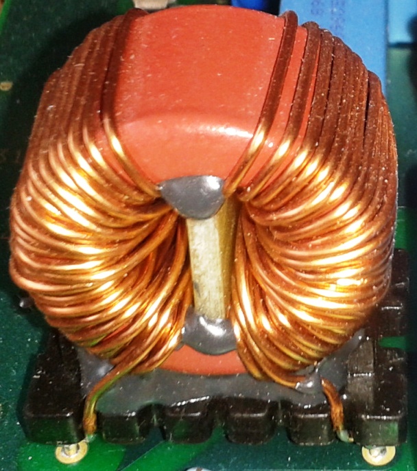
Lt1, Lt2, Lt3, Lt4 - inductance for subsequent turns (mutual inductance not shown),
Rt1, Rt2, Rt3, Rt4 - resistance for subsequent turns,
Cp1, Cp2, Cp3 - parasitic capacitance between the neighbouring turns

S. Zurek, E-Magnetica.pl, CC-BY-4.0
For example, the coil as shown in the picture above has multiple turns, and at lower frequency the whole coil can be considered as a single value of inductance (lumped inductor). But as the frequency of operation increases then capacitance between the turns will become non-negligible and eventually a resonance will occur between the lumped inductance of the whole component and the parasitic capacitance. Above this frequency the component will exhibit predominantly capacitive behaviour, until the next resonance caused by even lower-scale parasitic values.
transmission line!
Primary inductance
Secondary inductance
Parasitic inductance
In addition to their nominal role and value, electronic components such as resistors or capacitors always exhibit also unwanted parameter of parasitic inductance, because any conductor with current always produces magnetic field and thus there is always some inductance associated with it. In electronic components this is sometimes referred to as ESL (equivalent series inductance).76)
At sufficiently high operating frequency this parasitic inductance will affect the nominal value of the component, typically first making it behave as predominantly inductive (in that frequency range), through the local resonance point, then to be taken over by parasitic capacitance of even smaller features, to the next resonance, and so on. The exact response depends on the physical form, which dictates the values of parasitics.


S. Zurek, E-Magnetica.pl, CC-BY-4.0

S. Zurek, E-Magnetica.pl, CC-BY-4.0
In many circuits the parasitic inductance is low enough to be negligible, but in some cases it is critical to use special components which have especially low parasitics. For instance, a shunt resistor is utilised because voltage drop across it is directly proportional to current flowing through it - but only if the parasitic parameters are negligible. Therefore, it is important for high-frequency shunt resistors to exhibit low parasitic inductance. Otherwise, their impedance increases with frequency, and thus the voltage drop is no longer directly proportional just to the current (but also to the frequency).
For wire-wound resistors, the winding can be made in a special non-inductive way, e.g. by using the bifilar principle, Ayrton-Perry, or similar.


S. Zurek, E-Magnetica.pl, CC-BY-4.0
Coupled inductance
cde
S. Zurek, E-Magnetica.pl, CC-BY-4.0
Leakage inductance
leak
Variable inductance
var
Complex inductance
Real inductance and imaginary inductance
Real inductance and imaginary inductance
Real inductance and imaginary inductance
Internal, external, and total inductance
Every electric current generates magnetic field around itself. Physical conductors have final thickness, diameter, or cross-sectional area and therefore some amount of volume with magnetic field will reside within the conductor itself. Knowing the current density distribution (e.g. uniform) and the shape of the conductor (e.g. round wire) it is possible to calculate how much of the magnetic field is stored within the volume of the wire itself, and therefore this can be converted to the value of the partial inductance, which thus can be called internal inductance.77)78) For most conductor configurations the value of internal inductance is much smaller than that of its external inductance. Also, in the case of very high frequency currents the skin effect will prevent the current to penetrate into the body of the conductor, with the majority of the current flowing on the surface of the conductor. For a straight round tubular conductor with uniform current the magnetic field inside the tube turns out to be zero which means that there is no magnetic energy stored inside the tube, and therefore there is no partial inductance associated with it.
Contrary to the internal inductance, the external inductance is associated with all the volume of space outside of the conductor. Apart from special cases this is much larger than the inside of the conductor, and thus there is more energy stored outside of the conductor, and consequently the external inductance is much larger than the internal inductance.
The sum of the internal inductance and the external inductance is sometimes referred to as the total inductance, which then can be used as the value of the self-inductance.79)80)81)
Linear and non-linear inductance
Linear inductance

S. Zurek, E-Magnetica.pl, CC-BY-4.0
In idealised or simplified calculations carried out for a limited range (such as low-signal analysis), linear and proportional behaviour is often assumed. In such systems the energy is equal to coenergy, which is useful for some computations.

For example, air-cored inductors or chokes are constructed such that the magnetic field is stored in a paramagnetic or diamagnetic medium (such as air), which for ordinary practical reasons can be assumed to be linear. This is because saturation does not occur, or at least not in normally achievable levels of magnetic fields.
Non-linear inductance

S. Zurek, E-Magnetica.pl, CC-BY-4.0
However, all ferromagnetic-like materials exhibit magnetic saturation.

S. Zurek, E-Magnetica.pl, CC-BY-4.0

Energy and inductance
| → → → Helpful page? Support us! → → → | PayPal | ← ← ← Help us with just $0.10 per month? Come on…  ← ← ← |
Measurement of inductance
The value of inductance can be measured by several techniques, mostly including electrical signals of voltage and current, involving AC or transient conditions, with typical examples given below. The type of measurement is dictated by the type of inductance and the available equipment.
RLC or LCR meter
RLC or LCR bridge an meters - phase shift and amplitude88)
L/R time constant
rise or decay time