Table of Contents
Reed relay
| Stan Zurek, Reed relay, Encyclopedia Magnetica, https://e-magnetica.pl/doku.php/reed_relay |
| reviewed by Jeff Jones, 2023-11-20 |
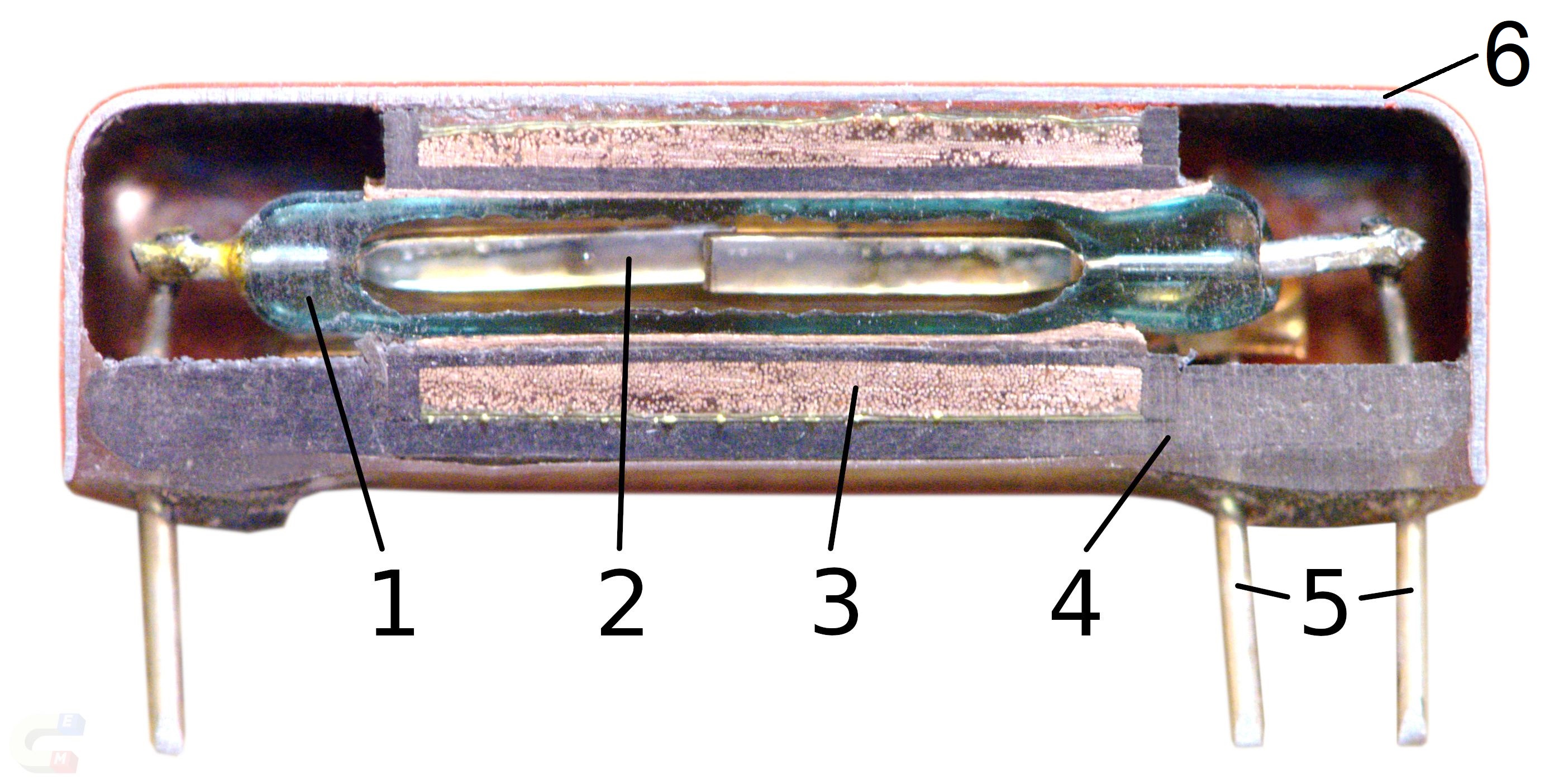
Reed relay or reed switch - a type of low-power electromechanical relay or switch used for switching signals by applying current to the activating coil. A reed relay has a glass tube with hermetically sealed magnetic flexible contacts (called “reeds”). Upon application of magnetic field the contacts are attracted to each other and the relay is switched on. And when the magnetic field is removed then the contacts open due to being spring-loaded.1)2)3)
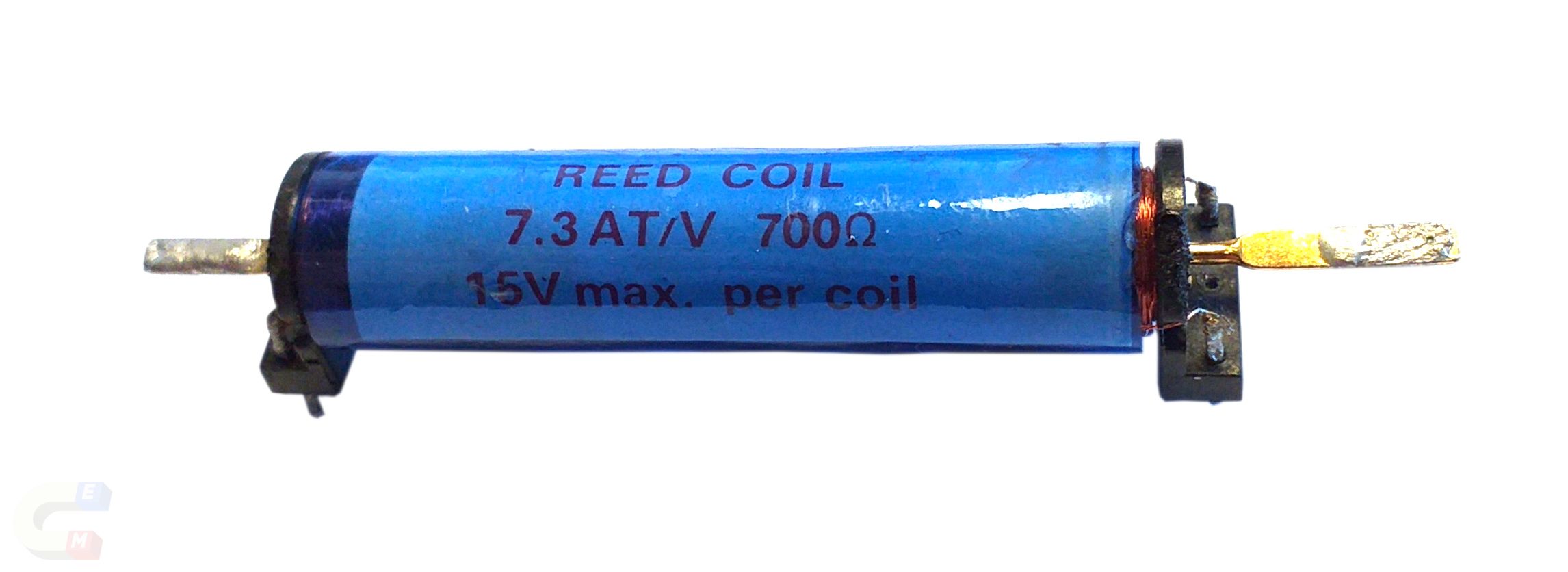
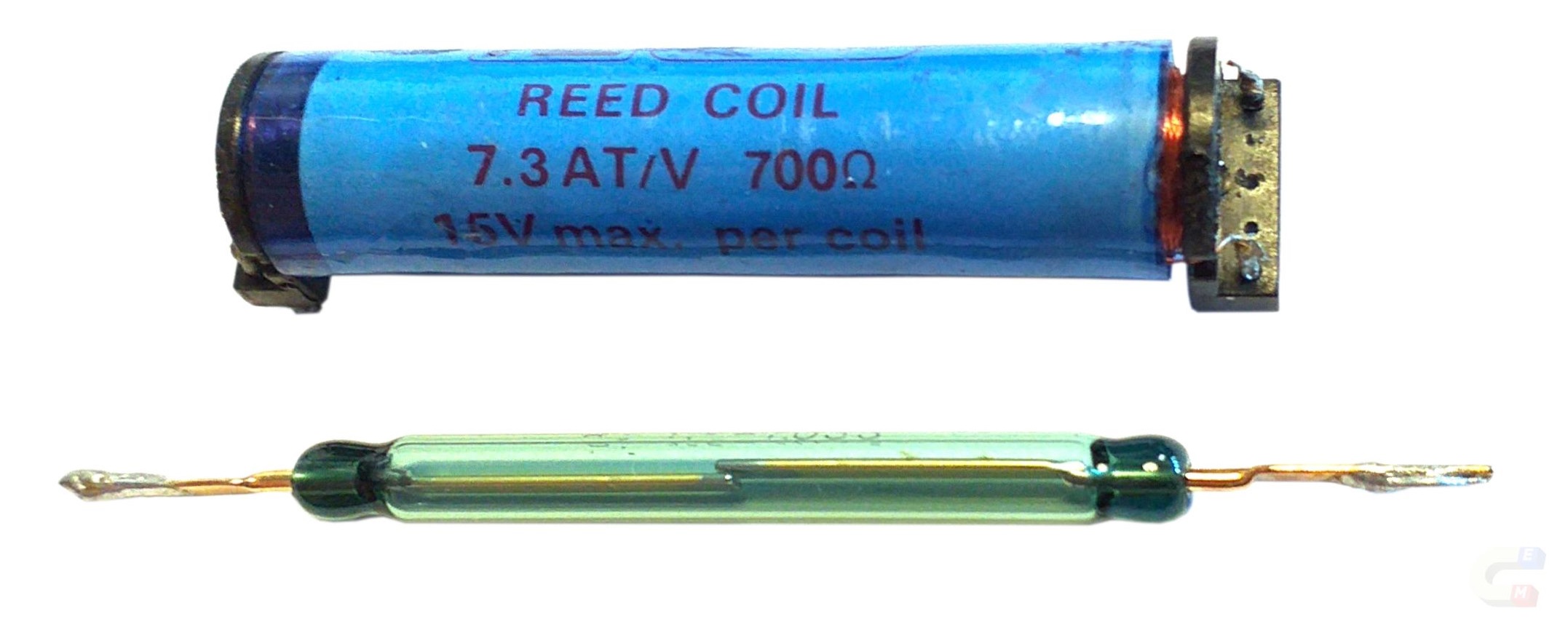
Typically, the whole device (glass tube and coil, with terminals or pins) is referred to as a reed relay, and the tube itself is a reed switch. A reed switch can be used to detect proximity of a permanent magnet and thus it can be referred to as a reed sensor.4)5)
S. Zurek, E-Magnetica.pl, CC-BY-4.0
It is possible to create a normally-closed reed relay by providing the biasing magnetic field from a permanent magnet which is fixed inside the same enclosure.7)
Reed relays offer natural galvanic isolation between the switched contacts and the magnetising coil (solenoid).
The pins (both: reeds or coil) can be directly solderable to the PCB, but also for high-voltage connections different methods can be used, such as spades.
| → → → | Useful article? Please link to this page to help us grow.  | ← ← ← |
|---|
S. Zurek, E-Magnetica.pl, CC-BY-4.0
S. Zurek, E-Magnetica.pl, CC-BY-4.0
Principle of operation
 by TubeTimeUS, and S. Zurek, CC-BY-4.0
by Pickering Electronics, license: YouTube
The internal contacts (reeds) are made from a metal alloy which is ferromagnetic. Once the magnetic field is generated by the surrounding coil the magnetic reeds will become magnetised. Their ends will be polarised with opposite magnetic poles and attract each other, and make electrical contact.
Therefore, in the simplest implementation a reed switch is “normally open” (form A). The “normally closed” (form B) version requires first providing a biasing magnetic field (e.g. from a small permanent magnet built into the coil), which has its polarity reversed with respect to the magnetising coil. Using the same principle as for the “normally closed” (with a bias magnet) it is also possible to make the “change-over” (form C) relays.
The inside of the glass tube can be filled with some chemically inert gas or with vacuum, so in any case it is hermetically sealed. Vacuum offers very good electrical insulation even with very small air gap between the electrical contacts, and this principle is also utilised in vacuum relays.
The reeds perform simultaneously several roles, and therefore their construction needs to take this into account:8)9)10)
- ferromagnetic - easily magnetisable by a moderate magnetic field (for closely-packed reed relays high-permeability magnetic shielding might be required)
- bending of external pins of the reeds can significantly lower their magnetic permeability to the point that they might become inoperable
- electrically suitable - for carrying the rated current
- chemically inert - so that the microscopic electric arcing does not degrade the contacting surfaces
- mechanically springy - to provide their own force for opening the contacts upon removal of magnetic field, but not too strong so that the relatively small applied magnetic field can move the contacts toward each other
- bondable to glass - so that the hermetic seal with the glass is not compromised over long term with thermal cycling, due to differences in thermal expansion coefficients
Magnetic forces

S. Zurek, E-Magnetica.pl, CC-BY-4.0
S. Zurek, E-Magnetica.pl, CC-BY-4.0
Design of a reed relay is a compromise between several competing effects.
The gap between the moving electrical contacts is required to be as large as possible in order to withstand the rated voltage when the switch is in the open position. However, from the magnetic viewpoint, large air gap represents high reluctance and reduces the available magnetic force, which might become below the threshold for the reeds to be pulled towards each other, so magnetically the gap should be as small as possible.
The reeds must be easily magnetisable so that they can be activated by small current in the coil, which makes the solution more energy efficient (the DC current in the coil is dissipated as power loss and heat across the coil's electrical resistance). However, the sensitivity to magnetic field cannot be too high, because stray magnetic fields from other nearby devices (perhaps the coil from the next reed relay on the PCB) could activate it. In the extreme case the Earth's magnetic field (around 40 A/m) could also activate a relay, depending on the direction of the field. For this reason, some relays are available with built-in magnetic shielding, or are manufactured in metallic/magnetic enclosure which acts as a shield. These solutions are useful for so-called “high sensitivity” relays (which can be switched with less current through the coil) or for “high-density” mounting, so that several relays can be mounted in the direct vicinity of each other.15)
Additionally, the reeds must provide the return force (also called restore force), which opens the contracts after removing the magnetic field. This requires a material with high magnetic permeability, low remanence and appropriate stiffness for retaining the spring action.16)
It should be noted that bending of the pins outside of the tube, as well as applying excessive heat during soldering can introduce internal stresses in the magnetic material of the reeds, which can both compromise their permeability, as well as the restoring force. For this reason the assembly of relays should follow the manufacturer instructions.
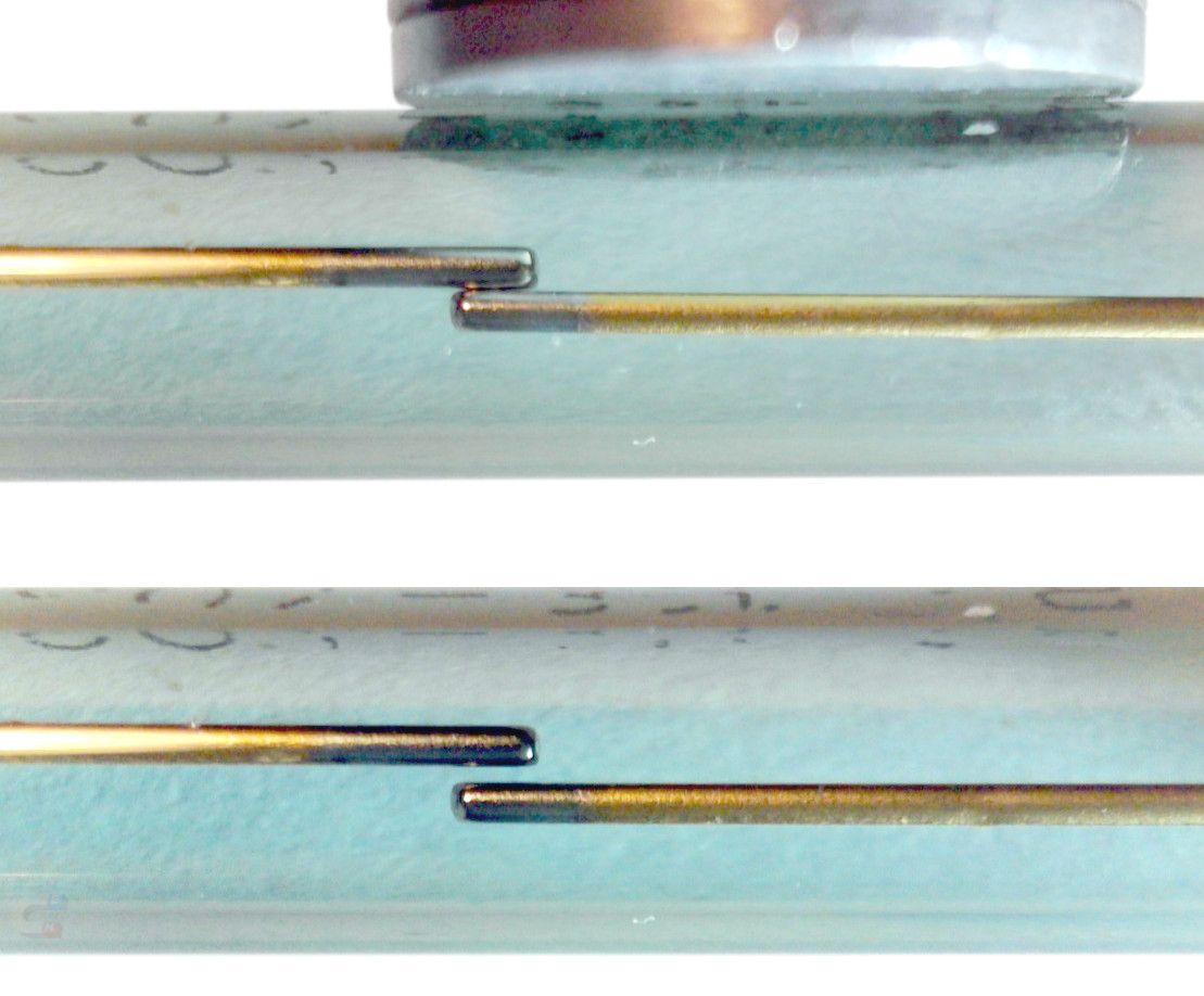
The magnetic field operates best if it is applied in the longitudinal direction of the reads. A uniform field applied in a transverse direction is likely not to activate the contacts. For example, in the picture as shown on the right the relatively small magnet had to be applied slightly towards one end of the tube to make sure that the contacts were switched. When this magnet was positioned exactly at the centre (i.e. symmetrically above the contact) then no switching took place. This is because with a symmetrical transverse magnetisation both contact ends would be magnetised to have the same magnetic pole, and thus they would not attract each other.
For a change-over version, there are three reeds and at least one must be movable and ferromagnetic. In the remaining two, the one providing the normally open function must be also ferromagnetic, but the normally closed must be non-magnetic.
| → → → Helpful page? Support us! → → → | PayPal | ← ← ← Help us with just $0.10 per month? Come on…  ← ← ← |
Electrical rating
Reed relays are typically used for low-voltage signal applications.17)18) However, they can be also produced for switching and withstanding high voltages up to 15 kV, which are useful for RF antenna and radar applications or insulation resistance testing.19)
Typical reed relays are designed to operated over ranges as follows (AC or DC current), with the highest ratings as listed below (but most switches have capabilities lower than this):20)21)
- Withstand voltage - up to 15 kV
- Switching voltage - up to 15 kV
- Carry current - up to 20 A
- Switching current - up to 3 A
- Coil voltage - standard voltages as for other relays (3, 5, 6, 12, 24 V, etc.)
- Contact resistance - between 10 - 250 mΩ
- Switching power - up to 250 W
- Contact capacitance - up to tens of pF (but can be below 1 pF)
- Magnetic screening - with or without
- Pull-in ampere-turns for contacts - up to 40 A-turns22)
- Insulation resistance between contacts - greater than 1 GΩ
- Life expectancy better than 106 switching operations
- Must operate voltage >75 % of nominal (e.g. 9 V for 12 V nominal)23)
- Must release voltage <10 % of nominal (e.g. 1.2 V for 12 V nominal)
The activation requirement is typically specified in terms of a nominal voltage that has to be applied to the coil. For example, a coil that has 700 Ω is to be supplied with the nominal 15 V, which results with a DC current of 21 mA, and power dissipation of 0.32 W.
Typically, the reed switches (glass tube with contacts) are specified for the activating magnetic field in the units of ampere-turn (AT, A-turns, or ampere-T), or ampere-turn per volt (AT/V), with typical values for larger switches being around 40 AT.
As with other types of relays, the typical specification gives guaranteed minimum activation above which the relay must operate, and a lower values at which the relay must release.24)
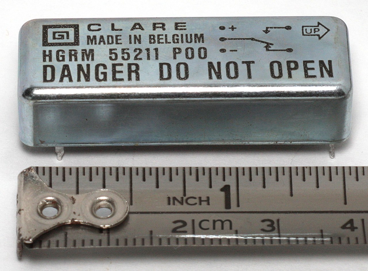
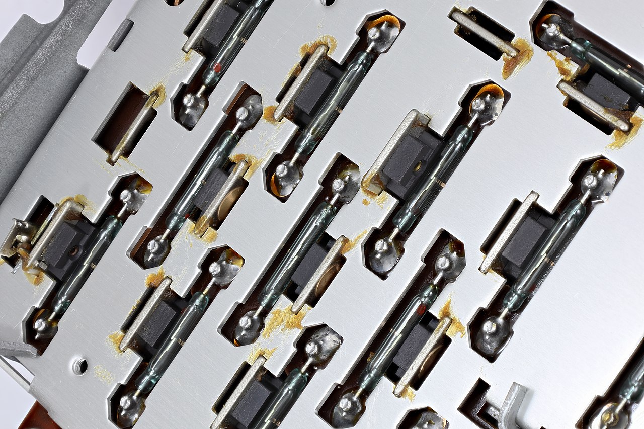
Examples of various reed relays and reed switches
 by Raimond_Spekking, CC-BY-4.0
 by Mister RF, CC-BY-4.0


